Applications Notes:
Automatic and self-recovery connections on Smartpack,
Smartpack II and Softools
|
|
Chapter 1:Use cases of automatic connection
Section 1.1:Remote access to a serial device
Section 1.2:Serial port replacement
Section 1.3:PSTN modem replacement
Chapter 2:Practical considerations and limitations
Section 2.1:IP address consideration
Subsection 2.1.1:Public IP for back-end application
Subsection 2.1.2:Public IP for cellular modems
Subsection 2.1.3:Servers with Dynamic IP
Section 2.2:Timing and delay issues
Section 2.3:TCP and UDP
Chapter 3:Configuring the modem
Section 3.1:Configuring the serial port
Section 3.2:Configuring the GPRS connection
Section 3.3:Configuring the IP connection
Subsection 3.3.1:Entering the TCP/UDP parameters
Subsection 3.3.2:Activating the automatic connection
Section 3.4:Testing the automatic connection
Chapter 4:Configuring the back-end application
Section 4.1:Timing and delay
Section 4.2:Virtual serial ports
Section 4.3:Virtual modems
Introduction
This application notes covers the process of using the Maestro modems to setup automatic TCP or UDP connections. This is applicable to the Maestro 100, Maestro 100evo and Maestro Heritage. Maestro 100 CDMA and Maestro 100 TD do not support this function. The Maestro Industrial can also establish such automatic connections, but is not convered in this document.
When used in automatic connection mode, the modem will automatically register on the GPRS or UMTS[A] [A]Maestro Heritage 3G only at startup, and create a TCP or UDP socket. As long as this socket is connecte to another end-point (usually a back-end application), the modem creates a bridge between the socket and its physical serial port: every received byte is forwarded from the socket to the serial port, and vice-versa.
Automatic connection is a very popular feature of the Maestro modems, that can give cellular Internet connectivity to virtually any serial device, even to those which have not been designed to work with modems.
Use cases of automatic connection
Remote access to a serial device
Few serial devices are designed to drive a modem, and even fewer have the necessary PPP stack to establish a cellular data connection. Nevertheless, you may need a remote access to the device. Be it an environmental sensor, a industrial controller, an I/O unit or the console interface of a network router, you can use the Maestro modem’s automatic connection feature for this.
The automatic connection features works by creating a logical bridge between the modem serial port and its cellular interface. Once the modem has activated its data mode, it will get an IP address and assign this IP address to your serial device, or will connect to a determined IP address (i.e. the IP address of the server on which your back-end application is running).
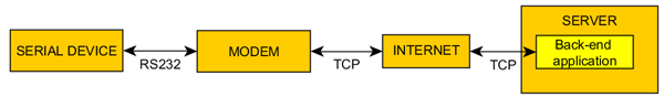
Figure 1.1 Data communication chain: remote access to a serial device
Once this is done, every byte of data received on the Internet side is forwared to the serial port, and vice versa. This is a transparent process for your device, and it is usually not required to change its settings.
Serial port replacement
Since many legacy back-end applications can not work with TCP or UDP sockets, it is possible to translate back the TCP/UDP data into serial port format, using virtual serial ports[B] [B]Virtual serial ports solutions are provided and supported by third-party companies.
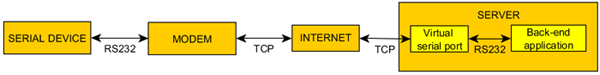
Figure 1.2 Data communication chain: remote access to a serial device using virtual serial ports
Using such ports, the serial port replacement will be completely transparent to both the serial devices and the back-end application, since both will “think” they are still connected to serial ports.
While this is an extremely convenient tool, virtual serial ports are not a very scalable solution: since operating systems limit the number of serial ports (Windows XP has a limit of 255 ports), it is not possible to do larger deployments using virtual serial ports.
For large deployments, direct TCP/UDP connection is a much better solution.
PSTN modem replacement
The use of PSTN modems in SCADA and AMR applications is very common, but due to the growing difference in price between voice communications and GPRS plans, it is tempting to upgrade deployments from switched circuits to packets communications.
Just like it is possible to use virtual serial ports to retrofit existing applications, it is possible to create virtual modems on the back-end server, that will react to AT commands the same way a regular modem would do, but which will “dial” IP addresses instead of phone numbers. These modems, provided by third-party companies[C] [C]Any virtual modem that supports raw TCP connections should work with the Maestro modems , are a drop-in retrofits and will work with the existing back-end software.
|
|
TOP
|
|
|
Practical considerations and limitations
IP address consideration
When establishing an automatic connection with a Maestro modem, it is necessary that at least one of the connection end-points (i.e. either the modem or the back-end application) can be reached by the other end-point. Typically, this consists of verifying that at least one of the connection end-points has a public[D] [D]A public IP address, also called “true IP”, is an IP address that is directly accessible from the Internet, and that is not hidden on customer’s or carrier’s private network. (and ideally fixed) IP address, and that a TCP port can be opened on this address.
Any end-point with a public IP address can be a TCP/UDP server. The other end-point will be the TCP/UDP client.
Public IP for back-end application
Most back-end applications do not have a direct access to Internet. They are often installed on a computer connected to a company local network, which will have Internet access through this company’s router and firewall.
Assuming that this company has a public IP address (which is often the case), it will be necessary that the company router is setup to make the communication port of the back-end application available from Internet (using NAT for example) as shown on figure2.1
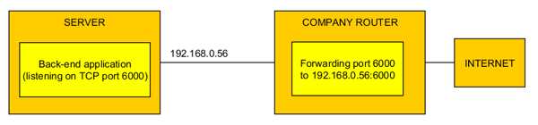
Figure 2.1 By using port forwarding it is possible to host a TCP/UDP server on a machine on the local network
If the back-end application does not support TCP/UDP ports, and you want to use serial port emulation software, then it will be necessary to open one port for each virtual serial port.
Public IP for cellular modems
There is a trend within network operator to assign mobile devices with private IP addresses (see figure 2.3↓), instead of public addresses (figure 2.2↓). Since these operators will ask their customer to pay some premium for public IP addresses, many customers prefer to let the back-end application be the TCP/UDP server.
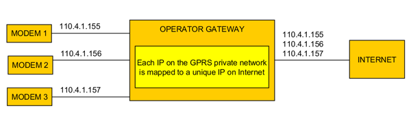
Figure 2.2 Cellular modems with public IP addresses. These modems can be used at TCP/UDP servers
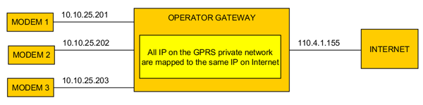
Figure 2.3 Cellular modems with private IP addresses. These modems can not be used at TCP/UDP servers.
However, if for some reasons you can not do this and you need the modem to be the TCP/UDP server, please contact your network provider to update your data plan.
Servers with Dynamic IP
Having a public IP is one good thing as it allows the client to see the server and connect to it. But the client also needs a fixed identification for this IP address, especially if the server gets a different IP address each time it connects to Internet.
If your ISP can only give you a dynamic IP address, it will be necessary to rely on a dynamic DNS service, such as DynDNS or No-IP. These are third party companies that will help to turn your dynamic IP address of the TCP/UDP server into a fixed hostname, which can be addressed by the client (cf. figure 2.4).
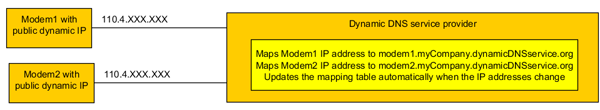
Figure 2.4 Dynamic DNS service providers help you resolve dynamic IP problem. You still need a public IP.
Timing and delay issues
A serial cable has negligible transmission delays. Every bit of information that is generated at one end of the cable is immediatly received at the other end, and the communication has no transmission problem. Most serial communication protocols and software that used serial port took this zero transmission delay for granted, and some even used this as integral parts of their communication methods (see figure 2.5).

Figure 2.5 Serial communication will assume a null transmission delay
his is a major issue when moving to cellular. Because of the very nature of the GSM network, GPRS communications have a long transmission delay, that can be more than one second. This means that every protocols and software that base some of their features on the transmission time may behave in unexpected ways.
The typical example is the one of a SCADA software that has a request timeout function. Everytime this software sends a request to a serial device, it will expect to receive an immediate answer, with a short timeout of 100ms. If no reply is received after 100ms, the software will interpretate this as a communication error. While this works fine in a pure serial environment, if the information is relayed over the GPRS network, where 250ms is a typical transmission delay, then the software will see a lot of errors (as shown on figure 2.6)
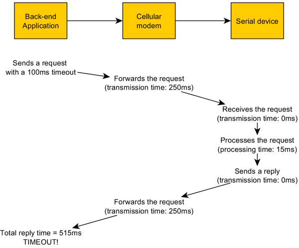
Figure 2.6 Cellular communication induces delay which may cause timing issues
If will be necessary, whenever possible, to change the sofware settings and extend any serial timeout to better fit values, for example two to four seconds.
TCP and UDP
The TCP and UDP protocol are different in their implementation. We will not enter in the very technical details here, but you need to know that:
- TCP includes an integrated acknowledgement mechanism. Every packet sent will have to be acknowledged by the recipient, or it will be considered lost and re-sent.
- UDP does not include this acknowledgement mechanism. If packets are lost on their way to the recipient, they will not be re-sent automatically
Both protocols have their pros and cons. While TCP is safer, it is also slower and has a higher data payload (if your operator charges you by the kilobyte of data, TCP will cost you much more than UDP). On the other hand UDP offers reduced latency and lower data payload, but packets have more chances to be lost in the network.
As a general rule, UDP is often prefered for streaming or very granular applications, where the loss of some data is not critical (sensors of slow varying signals, etc.); or when acknlowedgement/re-sending can be handled at the application layer (instead of the transport layer).
If data integrity is very important, or if the acknowledgement can not be handled at higher communication layers, then TCP will be preferred.
It is not possible to use both UDP and TCP at the same time.
|
|
TOP
|
Configuring the modem
Configuring the serial port
The very first thing to do is to gather vital information about your serial equipment, and especially its serial port. You need to know:
- What is the baudrate of the equipment (9600bps? 19200bps? 115200bps? another value?)
- What is the character framing and parity of the equipment (8 data bits/1 stop bit/no parity? 7 data bits/1stop bit/even parity? another value?
- Does the equipment uses hardware flow control? or no flow control?
- Is the equipment a DTE or a DCE? i.e. is the Tx pin of the equipment an input or an output?
The first three points cover the software serial port configuration. You then have to configure your modem to match exactly the same parameters as your serial equipment, using the following AT commands:
Configure the baudrate:.........................AT+IPR
Configure the character framing:................AT+ICF
Save these parameters in non-volatile memory:...AT&W
Configure the flow control:.....................AT+IFC
For details about the syntax of these commands, please refer to the AT commands interface guide document. Do not forget to change the settings of your terminal software as you reconfigure the modem.
If you do not like AT commands, you can use the modem’s configuration softwares provided by Maestro Wireless Solutions. The serial port parameters are in the “Network/Serial Port” tab (figure 3.1)
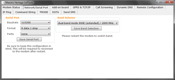
Figure 3.1 Configuring the serial port with the Maestro configuration tool
The fourth point will determine which kind of serial cable you will have to use. A GSM modem is a DCE, meaning that Tx pin is an input, and Rx pin is an ouptput. If your serial equipment is also a DCE, you have to use an RS-232 crossed cable (also known as “null modem cable”) to connect it to the modem. If your serial equipment is a DTE, you need to use a straight cable.
An easy way to identify your equipment is to remember that a PC is a DTE. If you use a straight cable to connect the PC to the serial equipment, then you will use a crossed cable to connect the modem to the serial equipment, and vice-versa.
Configuring the GPRS connection
It is then necessary to instruct the cellular modem how to connect to the GPRS network. This is done by entering the APN, APN username and APN password given by our service provider with the AT+IPGPRS command:
Command Syntax
AT+IPGPRS=1,<APN>,
<UserName>,<Password>
Response Syntax
>,<UserName>,<Password>
Examples:
AT+IP
+IPGPRS: 1,<AP
NGPRS=1,"internet","",""
","johnDoe","12345"
AT+IPGPRS=1,"mySpecialAP
N
Note that depending of the network operator and the subscription type, APN username and password may be blank.
If you get an ERROR message when configuring the APN, it may be because the value-added function pack is not activated in your device.
You can check this with the following command:
AT+VAFV
This command will return the version of the Smartpack, SmartpackII or Softools that is installed on your modem. If this command returns an ERROR, the function pack may not be activated. Enter this command to reactivate it:
AT+WOPEN=1
If you still can not configure the APN at this stage, the function pack may not be installed in your modem. Please contact your Maestro Wireless Solutions sales contact, FAE or local distributor for more details and application loading instructions. Please note that function packs are not installed by default on all Maestro modems, and may have to be purchased separately.
Using the configuration software, you can set the GPRS from the “GPRS & TCP/IP” tab (figure 3.2↓). The configuration software will not start if the function pack is not installed on the modem.
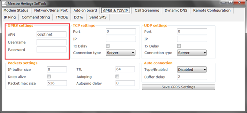
Figure 3.2 Configuring APN with the Maestro configuration tool
|
| |
Configuring the IP connection
In this third step you will have to enter the TCP/UDP parameters in the modem.
We will show here how to configure a TCP socket using AT+IPTCP and AT+AUTOTCP, but if you are working in UDP mode, you can follow the same guidelines, only replacing these two commands by AT+IPUDP and AT+AUTOUDP.
Entering the TCP/UDP parameters
The first command to type is AT+IPTCP (resp. AT+IPUDP):
Command Syntax
AT+IPTCP=<port>,<mode>,<address>,<TxDelay>
Response Syntax
mode>,<address>,<TxDelay>
Exemple
Server:+ IPTCP:<port>,
< AT+IPTCP=6000,"S","255.255.255.255",0
0
Client: AT+IPTCP=6000,"C","110.4.1.221"
,
Modem as server
If the modem is a server, the parameters are :
- Port is the listening port. The modem will accept incoming connections on this port only, and once a client is connected it will establish a logical bridge between this port and its RS232 interface
- Mode must be set as “S”, for server
- Address is an IP address, that can be used to filter incoming connections. If it is set to “255.255.255.255”, it will accept connections from any client. If it is set to a specific IP address, only this IP address can access the serial port.
- TxDelay determines if there is time delay introduced before sending a TCP frame that has not been entirely filled with user data. If it is set to 0 initiates the sending of a TCP frame as soon as possible after the reception of a single character value from the host. If it is set to 1 initiate a delay will be introduced before the sending of a TCP frame.
Modem as client
If the modem is a server, the parameters are :
- Port is the server port. The modem establish connection on the server to this specific port only.
- Mode must be set as “C”, for client
- Address is the IP address of your server. If you are hosting the server on your company’s network, this should be the Internet IP address of your company router, not the IP of the server on the LAN.
- TxDelay determines if there is time delay introduced before sending a TCP frame that has not been entirely filled with user data. If it is set to 0 initiates the sending of a TCP frame as soon as possible after the reception of a single character value from the host. If it is set to 1 initiate a delay will be introduced before the sending of a TCP frame.
Choosing whether the modem is a client or a server will only make a difference during the connection initialization: once the connection is established, the modem will try to maintain it all the time, making it is a real bi-directional data link. Data transfer can be initiated by both the server and the client once they are connected.
Activating the automatic connection
Once all the parameters are setup, it is time to actually activate the automatic connection. This is simply done by sending the command :
AT+AUTOTCP=1
After this, you can reboot the modem. The automatic connection function actually starts twenty seconds after the modem is switched on or reset. During the first twenty seconds, the modem works in normal AT commands mode. In this mode, it is possible to deactivate the automatic connection function with:
AT+AUTOTCP=0
Using the Maestro configuration software, these settings are entered on the “GPRS & TCP/IP” tab. On figure 3.3↓, the green box is equivalent of the informations entered with the AT+IPTCP command. The blue box is for the AT+IPUDP command (you only have to fill one of these two groups), and finally, the red box is to select whether the automatic connection is done in TCP mode, UDP mode or is disabled (equivalent to AT+AUTOTCP=1, AT+AUTOUDP=1, or (AT+AUTOTCP=0 and AT+AUTOUDP=0)). Buffer delay refers to the AT+AUFCM command.

Figure 3.3 Configuring the TCP and UDP parameters with the Maestro configuration tool
Testing the automatic connection
Before going further, it is a good idea to test the setup now. It can be easily done with a PC and some virtual serial port software. For testing purpose, the tool VSPE from Eterlogic has shown pretty effective.
If the modem is a server, create a new TCP client serial port and have it point to the modem’s IP address. If the modem is a client, create a new TCP server serial port and make sure that it is available to the modem (that you have the IP that is entered in the modem, and that your company router is correctly setup).
Then, open two terminal windows, one connected to your virtual serial port and one connected to your modem (trough the physical serial port). Twenty seconds after the modem startup, the connection should be established. Send some characters into one terminal, the same data should appear after a short delay on the other terminal.
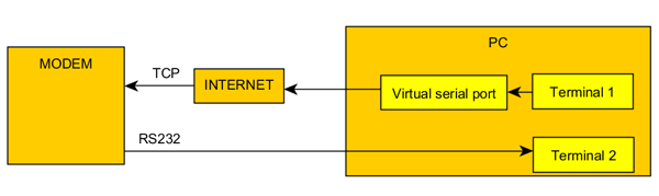
Figure 3.4 Basic test setup
|
|
TOP
|
Configuring the back-end application
Timing and delay
As explained in section 2.2, the cellular modem has a non-negligible transmission delay, due to the nature of the cellular network. A lot of back-end applications usually have a timeout delay to detect errors in the communication chain, which is often tuned to very short times.
It is recommended to increase this timeout delay to a value of several seconds (two to four) so that the application’s behavior is not affected by the new setup.
Virtual serial ports
If your back-end application was relying on serial ports, it will now have to work with TCP or UDP sockets instead.
Many older applications can not support such mode. It is then necessary to use virtual serial ports devices. A virtual serial port is a piece of software, designed by a third-party company, that runs on your PC and will create any number of emulated serial ports on it. These virtual devices will be seen as real serial ports by your applications, but instead sending data to a physical port at the back on the computer, they will send it to TCP or UDP sockets, accross the Internet.
This allows your serial-port-only application to connect with TCP/UDP sockets.
The automatic connection feature of Maestro modems has been successfully tested with virtual serial ports solutions from Eltima and Eterlogic. Please refer to the documentation of these solutions to setup instructions and support.
Note that you can not add more virtual serial ports than the maximum limit of your PC operating system. Under Windows XP for example, you can not have more than 255 serial ports.
Virtual modems
Virtual modems work in a similar manner as virtual serial ports, except that they will offer an AT command interface to your application, so that it can tell the modem which end-point to reach. It will be necessary to replace the phone numbers list in your application with the IP addresses and port numbers of your new modems.
Using a virtual modem, you will mostly need to use the Maestro modem in TCP server mode, so that it can be called by the virtual modem. If the Maestro modem is a TCP client, it will establish the connection. Make sure that your virtual modem application can support incoming connections in that case.
Virtual modems solution COM/IP from Tactical software has been successfully tested with Maestro modems, however any solution that support raw TCP connection should work as well. Please refer to the documentation from the virtual modem supplier for setup instructions and support.
|
| |
|